Quality & Delivery
Bowing and Skewing in Lace: Reference Lines and Pattern Distortion
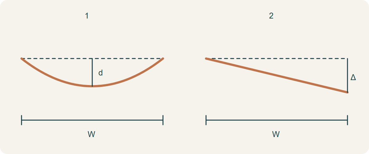
Bow is a curved departure of a crosswise reference; skew is an oblique departure from a reference perpendicular to the length direction. Lace adds a complication: embroidery rows, scallops and underlying yarns may not share a reference line. Establish what should be straight from the approved design, then measure it relaxed on a defined width. A diagonal flower by itself is not proof of distortion.
1. Identify the structural and decorative references
In a woven fabric, a filling-yarn line is a relevant crosswise structural reference; in a knitted fabric, a course may be relevant. On embroidered net, a motif row can be visually important while not corresponding to either. Ask for the ground construction and the approved artwork or physical repeat reference. Record the ground line and the embroidered alignment separately so a correctly sloping motif is not reclassified as a defective yarn line.
ASTM D3882’s public scope distinguishes woven filling, knitted courses and printed geometric designs. That scope supports careful reference identification, not the assumption that every decorative branch is a test line. A formal report on another construction requires laboratory agreement on applicability and the actual current method. The simple geometry below is an explanatory project check, not a reproduction of the complete licensed procedure.
Technical references
2. Build a baseline that the cloth does not move to fit
Support a sufficiently broad representative section and allow the agreed preparation before observation. Identify the length direction and a baseline perpendicular to it. Trace the chosen crosswise reference without pulling one edge to make the motif square. If an irregular selvedge cannot establish length direction reliably, use the agreed ground or design reference and record that choice; a scallop peak is not automatically a straight selvedge.
Mark the two width endpoints and state whether the assessed width is full, usable or a bounded panel width. Take a square-on photograph with a scale and retain the marked sample where practical. A camera held at an angle can make straight lines look oblique, while hand-stretching can hide relaxed bow. Compare several positions along the roll; one favourable cutting cannot establish the maximum distortion or uniformity of an entire roll.
3. Distinguish a curved line from a tilted line
For a simple bow sketch with endpoints aligned at the same lengthwise level, connect those endpoints with a straight crosswise baseline. The maximum perpendicular departure d from that line describes bow depth. With a straight but skewed reference, measure the lengthwise difference Δ between its two width endpoints relative to the perpendicular baseline. Do not use the length of a curved or diagonal yarn as the denominator for the explanatory percentage.
For this explicitly defined project sketch, bow percentage = d ÷ W × 100 and skew percentage = |Δ| ÷ W × 100, where W is the stated crosswise reference width. If skew and curvature occur together, retain the complete traced line and agree how they will be separated; do not force a complex S-shaped or tilted curve into the simple drawing. The contract or formal method may define more detailed treatment and must control an acceptance decision.
4. Recalculate the width and displacement together
Hypothetical bow: a 1,400 mm assessed width has aligned endpoints and a 21 mm maximum depth. The explanatory bow ratio is 21 ÷ 1,400 × 100 = 1.5%. Hypothetical simple skew on a separate sample: a 28 mm end difference across the same 1,400 mm width gives 2.0%. Neither value is automatically acceptable or unacceptable; the agreed specification and the garment’s visible geometry decide that.
If another inspector uses only a 700 mm panel, that is a different reference interval and must be reported with its own endpoints and depth. Do not reuse the 21 mm full-width maximum and simply halve the denominator to create a more alarming panel percentage. Locate the panel on the traced line, measure its actual departure and examine the piece as it will be cut and joined.
| Illustrative condition | Displacement | Defined reference width | Ratio |
|---|---|---|---|
| Simple bow, aligned ends | d = 21 mm | W = 1,400 mm | 1.5% |
| Separate simple skew sample | Δ = 28 mm | W = 1,400 mm | 2.0% |
| A narrower garment panel | Measure again on its own interval | W = actual panel interval | Do not copy full-width d |
5. Check borders and mirrored pieces on the actual pattern
Lay the pattern with its intended grain or agreed structural direction, then compare visible motif alignment and seam-match points. For a straight border, check the line used by the finished hem, not merely the nearest decorative peak. A bowed repeated border can move away from a straight hem allowance, and correcting by rotating the pattern may sacrifice the required ground direction or counterpart match. Document the trade-off rather than concealing it in extra seam allowance.
A symmetrical pair may need both halves traced independently; moving one panel to a nearby motif may change shade, sequin direction or border height. If the distortion prevents the agreed layout, stop cutting that section and discuss its disposition. A defect map can identify unaffected runs, but it does not establish that stretching or steaming the affected run will permanently correct it.
6. Correction is a process trial, not a hand-pulling promise
Industrial equipment makers distinguish bow and skew correction mechanisms. That shows why the two shapes should be identified separately; it does not mean every embroidered or sequined net can pass through a straightener safely. Heat, tension and layer interaction can change the ground, thread and decorations differently. Any proposed reprocessing needs a representative trial and checks appropriate to the complete construction and intended care.
After a trial, remeasure in the same agreed relaxed state and compare the retained untreated reference. Recheck width, motif repeat, handle, attachment and any changes after the planned care. If acceptable alignment lasts only while the cloth is held under tension, it is not evidence of a stable correction. Keep the process revision and results tied to the roll so a later repeat order does not rely on an unrecorded temporary fix.
Technical references
7. Questions that establish a useful acceptance record
Is every diagonal motif skew? No; compare the approved design and structural reference. Can an average hide a local problem? Yes; retain local measurements and positions. Does a short edge sample prove the full width is straight? No; the reference must span the width being assessed. Is a percentage enough to order a remedy? No; include the traced shape, endpoints, material state and garment consequence.
Independent inspection can verify the agreed geometry and locate affected runs; garment trials can verify the chosen layout. Neither proves an untried correction process or universal suitability of the material. Combine these distinct records before release, and make the acceptance limit, maximum/local reporting rule and excluded sections explicit in the order.
Discuss your embroidery project
Send All4Lace a square-on full-reference photograph, width and displacement measurements, the approved motif direction and the affected garment pattern. Keep structural and decorative reference lines identified separately.
Contact Zhijin